

A contact switch is used to regulate whether or not an electrical current is passing from a power source and into an electrical device. These switches are found in many types of equipment and they are used to control, for example, the power output from a wall socket into a device when it is plugged in; the currents passing across the circuit board of a computer; or the electricity powering a light bulb when the switch is flipped on. Because of their prevalence, simulating contact switches is a fundamental step in designing electronic applications. Since the concept used in their design remains much the same even as more complex components are implemented, a simple model can be used to provide a basic understanding of how a contact switch works. We can find such a simulation in our Model Gallery, and can use this model to explore the mechanical, electrical, and thermal behavior of the two contacting parts of the switch.

Contact switch showing temperature distribution and current density within the switch.
Contact Switch Concepts: Mechanical Contact and Electro-Thermal Contact
The working principle behind a contact switch is simple — two conductive pieces of metal with an electrical voltage difference across them are brought into contact, allowing a current to flow between them. The metallic surfaces of the two components that touch one another are called contacts, and when the connection between the two contacts is broken, the current stops flowing.
The current flow between the two contacts contributes to an increase in temperature in the switch due to the Joule heating effect. Anyone who has felt a warm power plug after running a vacuum cleaner, for instance, has experienced this effect. The heating of the contact switch can change the material properties of the metal as well as the surface area of contact, and therefore is an important effect to consider when modeling the switch. Letting the temperature become too high can even cause the switch to burn out, meaning the switch is no longer functional. Therefore, it is important to analyze its current-carrying capability in order to prevent this from happening. It is also important to consider that when the two metallic pieces come into contact, the surfaces touching each other experience a mechanical pressure or contact pressure. This mechanical pressure on the contacts can alter the electrical and thermal properties of the material locally around the region surrounding the contacts. Therefore, in order to accurately simulate the current-carrying capability and temperature rise in the switch, it is important to take a more comprehensive approach in the simulation and incorporate the effect of contact pressure to compute the electrical and thermal conductance of the contact surfaces.
Let’s find out how you can combine all these concepts together to model a contact switch.
Modeling Electrical, Mechanical, and Thermal Conductance in a Contact Switch
First, let’s look at the geometry and materials used to build the contact switch. The switch is made of copper, with two fixed cylindrical elements and a central region where the contacts are located. On the end of each contact are plate hooks that enable contact between the two pieces. In the simulation, an electric potential of 1 mV is applied to the left side of the switch, while the right side is grounded. The geometry of the contact switch is shown below:

Contact switch geometry, showing two fixed cylindrical bodies and the contacts at the center.
The exposed surfaces of the switch lose heat due to their interaction with air via natural convection. In the simulation, this is modeled by specifying a heat transfer coefficient and the ambient temperature of the surrounding air (a more ambitious simulation might also include the fluid flow of the air). The model first solves for structural contact to obtain the contact pressure on the contact surfaces. These results are then used to compute the electrical and thermal conductance of the contact’s surfaces in a Joule heating simulation.
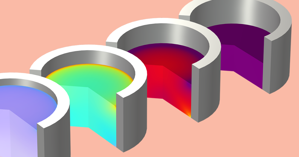
We can use the simulation to analyze the electric potential distribution in the switch as shown below:

Profile of the electric potential distribution in the contact switch.
As would be expected, the electrical potential ranges from 0 V (ground) on the right, to the applied 1 mV on the left.
Initially, the contact switch is assumed to be at room temperature (293.15 K, 68°F, or 20°C). A potential difference across the two components in the switch creates a current flow, which in turn leads to Joule heating. This causes a rise in temperature in the switch. If you leave the switch on for a while, temperature distribution in the switch reaches an equilibrium as shown in the figure below:

Temperature distribution in the contact switch.
In this model, Joule heating causes the temperature in the switch to rise about 5 K above room temperature, although only a small temperature variation is seen within the switch itself. Introducing the effect of electrical and thermal conductance allows us to predict the temperature rise more accurately. The simulation also shows that the switch gets slightly hotter at the contact region.
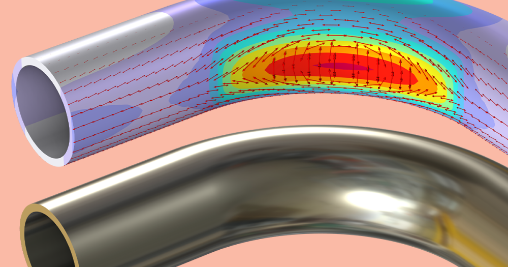
If we look at both the temperature distribution at the contact region, and current density within the switch, we can see the results shown below:

Temperature distribution (surface plot) and current density (streamlines) at the contact region.
The simulation confirms that where the two hooks are touching at the center of the switch, the electrical current (shown as streamlines) passes from one hook into the other.
Extending the Simulation Using COMSOL Multiphysics
In this simulation, we showed how the contact pressure occurring between the two contacts can affect the electrical and heat conduction behavior in a contact switch. In some cases, it may be beneficial to conduct a more in-depth analysis by taking more physics effects into account. This can be accomplished using the electrical and thermal contact boundary condition that was added to COMSOL version 4.3b. With these new features, we can include additional analysis, such as:
- Measuring the degree to which the electrical or thermal conductance varies in relation to a change in pressure on the contact surface, or change in surface roughness and hardness, with the Constriction Conductance feature
- Testing how a thin layer of air, dirt, or fluid between the contact surfaces would change the electrical and thermal conductance, using the Gap Conductance feature
- Measuring the radiation that could occur across the microscopic gap between the two contacts depending on how hot the temperature of the system became, using the Radiative Conductance feature
It would also be possible to add more features to this simulation, such as the temperature-dependency of material properties and thermal expansion as a result of Joule heating.
Each of these new features can be added to the model to construct a simulation that is more accurate for the particular environment and application where it will be used. To learn more about the implementation of these features, you can attend the upcoming Simulation of Thermal-Structure Interaction webinar that will be given on August 15th by my co-worker Supratik Datta and Kyle Koppenhoefer of AltaSim Technologies.
Model Download
Before attending the webinar, you can download the contact switch model, Simulation of Multiphysics Contact in a Power Conductor from the Model Gallery to explore how the mechanical, electrical, and thermal interactions in the contact switch were simulated.


Comments (5)
Isaac Vicedo
October 15, 20131mV why?. Can be configured to 1000 Ampers for a same voltage for example at 240 Volts
Alexandra Foley
October 22, 2013Yes, you can of course model with different driving voltages, or driving currents, depending upon your needs.
Isaac Vicedo
November 1, 2013Thanks Alexandra
I can see any example in the web? I don´t find any. I look in the options of comsol physics but do not know which one to use.
Please help me.
Muhammad Shah
January 24, 2017Hello,
Can anyone tell, when we use “Terminal” in electrical current
the current and voltage we applying is AC or DC ?
Caty Fairclough
January 24, 2017Hi Muhammad,
Thank you for your question. You may find this blog post helpful: https://www.comsol.com/blogs/control-current-and-voltage-sources-with-the-acdc-module/.
If you have any further questions, please feel free to reach out to COMSOL Support.
Online support center: https://www.comsol.com/support
Email: support@comsol.com
Thank you!
Best,
Caty